
Rocker Geometry
The performance of an engine is dependent on a number of systems, where each individual system works in sync to influence the final result.
The performance of an engine is dependent on a number of systems, where each individual system works in sync to influence the final result. The valve train is one of those systems and correct rocker geometry is critical, as it makes a significant difference to engine power and durability.
Valve movement is affected by the location of the rocker. Locating the rocker correctly can be achieved by moving mounting points, combining different length pushrods and valve stems, or changing rockers. But what is the correct rocker position?
The tip of the rocker should operate around the centreline of the valve stem when the rocker opens the valve. Incorrect contact between the rocker and the end of the valve stem can cause side loading on the valve, erratic valve movements, loss of valve lift and rocker binding. All of these problems can lead to loss of performance or valve train failures.

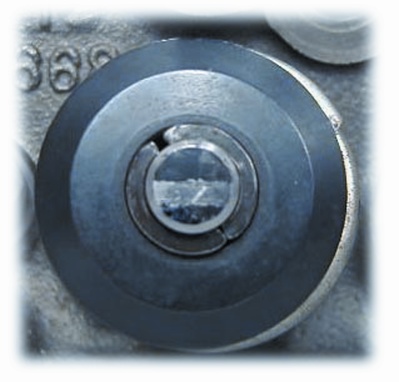
Fig 1: The contact patch on the valve tip should be between 1.5mm and 2.0mm. The patch slightly off valve centre is preferable to a wide contact in the centre of the valve.
A process can be performed to check this roller/valve tip relationship. To view the process for solid lifters, click here. To view the process for hydraulic lifters, click here. (see the bottom of this page)
If the tip of the roller contacts the stem towards the outside of the head, the pushrod is too long. Or if the contact is toward the intake side of the head, the pushrod is too short.
|
The pushrod is too long. The patch is wide and shifted to the exhaust side of the valve tip. |
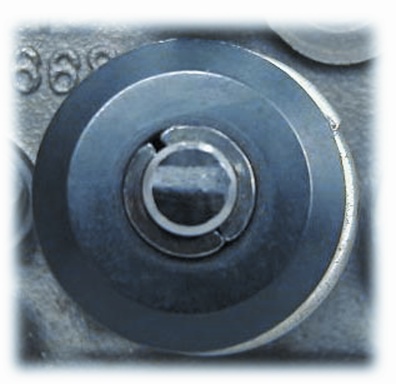
The pushrod is too short. The patch is wide and shifted to the intake side of the valve tip. |
The pushrod is the correct length. Notice that the patch is narrow and central on the valve tip. |

HYDRAULIC LIFTERS
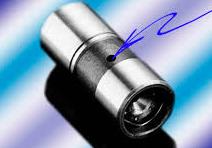 |
Hydraulic lifters have a small hole in the lifter body, which is supplied oil under a consistent pressure via an oil channel. The lifter is free to fill with oil while the valve is closed. As the cam enters the lift phase, the check valve inside the lifter shuts. As oil does not compress, full cam lift will now be transfered to the pushrod. |
The diagram below shows the internal structure of a hydraulic lifter. A preload is applied to the lifter so that the plunger is positioned away from the circlip.

To determine the correct rocker geometry when hydraulic lifters are being used, a slightly different method needs to be employed, than setting up with solid lifters. As there will be no oil pressure to fill the lifter with oil, the lifter has no oil to compress, so the adjustment in the pushrod is taken up by the lifter. Therefore, there will be an incorrect result. Click here for the process which can determine the correct pushrod length required when using hydraulic lifters.
 |
 |
| Click here for the pdf version of the process which can determine correct pushrod length when using solid lifters. | Click here for the pdf version of the process which can determine correct pushrod length when using hydraulic lifters. |


